Tutorial 02: Plasma Vent
In this tutorial you will learn how to create simulations with only fire present. Moreover, you will control the opacity to make a flame transparent and you will also learn how to create a collision container. Finally, you'll see how you can tweak your settings visually AFTER you've run your simulations and add post-process effects to the results.
In 3ds Max, select File->Open, and from your /Scenes/FumeFX/ Tutorials folder, select the file Tut_02_start.max.
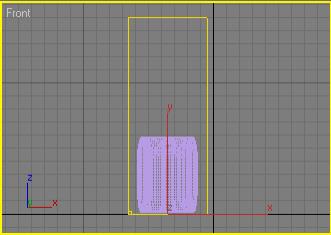
After the file loads, create a FumeFX Grid so that it encompasses the entire Engine as is approximately 150 units high as shown below.
Now, in the last tutorial, you created a FumeFX Geometry Source helper in the viewports and assigned the object from the command panel so that it could be referenced in the FumeFX simulation. This time, we're going to do it a bit differently to show you another way.
Go to the Helpers section of the Create Command Panel and choose FumeFX.
Next, select an Object Src from the list and drag it out in any of the viewports.
Now, re-select the FumeFX Grid object and go to the Modify Command Panel.
Press the FumeFX UI icon button to open up FumeFX's interface.
Select the Obj/Src tab and choose the FumeFX Obj Source that you have just created.
Right now, the Geometry Source in the FumeFX UI dialog doesn't reference any geometry in your scene. But we can easily fix that.
With the FFX Object Src01 highlighted in the FumeFX UI dialog, go to the Geometry Source Parameters rollout and click the Pick button.
Choose the Cone01 object as the geometry to be used within the simulation.
Note: You may want to hit the H-key to select the geometry for FumeFX to use.
Now, with the source selected, we now need to set up collision geometry for FumeFX to use within its simulation.
Still within the Obj/Source panel in the FumeFX UI dialog, click the Pick button again.
This time, click directly on the geometry in the scene named Case.
You will notice a few things here once you select the object. Instead of the new entry coming up with the letter 'S' in the Objects/Sources/SpaceWarps list (like what precedes the FFX Obj Source01 entry), it shows up with the letter 'O'. This indicates what sort of node it will represent in the simulation. Sources show up with S, and other objects show up with O. When you have complex scenes, this can be a very handy way of determining what each entry is doing.
Additionally, a completely different set of parameters comes up when you select on the Case object in the dialog.

You'll notice that there are only a few options available to an object in your simulation. Basically, FumeFX is asking how you want this collision object to be handled by the simulation engine.
Since we are only worried about the inside of the jet case, make sure Solid is selected.
Before you move on, select the FFX Object Src01 in the list, and within the Temperature group of controls, change the Amount spinner to 600. By increasing the temperature setting, everything will rise faster due to buoyancy.
Next, you'll set up some of the parameters for your simulation. Since this is a sci-fi engine, the amount of smoke we want to produce is very small, and as such, to speed up our simulation, we're going to turn it off and prevent it from being exported as part of the solution.
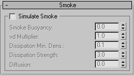
Select the Simulation tab within the FumeFX UI floating dialog, and scroll down to the Smoke rollout.
Click on the Simulate Smoke checkbox to de-activate it. This will allow us to exclude smoke calculation from the simulation.
Next, within the Simulation group of controls, make sure that Advection Stride is set to 0.3.
These settings will help make sure that the flames coming from the vent do not slow down too much as they move away from the source and dissipate.
Under the Temperature group of controls, set the Temperature Buoyancy to 2.0.
Higher buoyancy will help the plasma rise faster.
Also set the Vorticity spinner to 0.4 and set the X Turbulence spinner to 0.4 as well. This will give the plasma flames some subtle waves and natural motion.
After this, go to the Fuel rollout and set the Ignition Temperature to 0, Burn Rate to 12, Burn Rate Variation to 0.2 and Expansion to 0.6.
These settings work in concert to determine how fast and hot the fuel will burn and how much pressure it puts on the simulation volume.
Next, select the General Tab and set an output path from the Output rollout. If you followed our suggestion from the first tutorial, simply create a new folder called \Tut02 under the \FFXSimData folder and use it for the jet engine simulation data.
While you are in the General tab, make sure the Spacing spinner is set to 2.0. We don't want super detailed plasma flames, and this setting will also help keep sim times low.
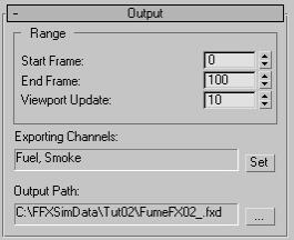
Next, click the Set button within the Exporting Channels: section to bring up the Select Channels For Output dialog.
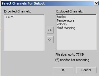
If it isn't already in the Excluded Channels window, select the Smoke entry in the Exported Channels window, and click the double-arrow button so it moves into the Excluded Channels window.
Then click OK to close this dialog.
The only channel we want to export is Fuel as shown below.
Now select the Render tab and scroll down to the Fire rollout.
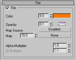
Within the Fire rollout, set the Color spinner to 9.0 and the Opacity spinner to 0.1.
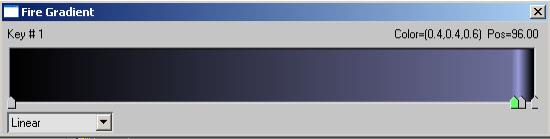
Now right-click on the Color swatch and choose Key Mode.
Try to match your Fire Gradient to look like the example below. What you're going for is a dark gray-blue with a small slice of light gray-blue at the center of the flames. Our plasma is going to have a blue tint to it to start. To understand the gradient, try to remember that the left-most edge represents the edges of the flames, while the right-most edge represents the core of the flames. So in this case, we want the flames dark on their outer edges and more solid towards their centers.
Next, you need to create an Animation Flow Curve to control how the Opacity of the flame is handled.
Click on the AFC button (it is active by default) to open the curve editor.
Now the default curve is not what we want, so click the Delete button (the small X) to reset the AFC curve to it's default linear state.
Next, move the two end points of the curve to match the position of the curve shown below, and then add a point roughly in the middle to give it some curvature.
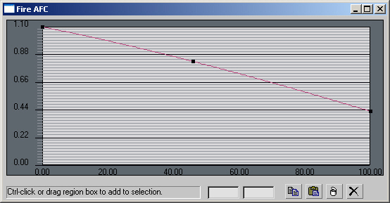
When done, close the Fire AFC dialog.
Now, let's do a quick check:
FumeFX UI placed where we want the simulation to occur? CHECK.
FumeFX Geometry Source helper created to reference our scene geometry to be used as a fuel source? CHECK.
Other scene geometry selected to be used as a collision object in simulation? CHECK.
Simulation channels determined and set up (remember turning off the Smoke channel)? CHECK.
Simulation parameters adjusted for a sample run? CHECK.
Alright then - you are ready to run your simulation and see what you've got.
Before you start your simulation, let's enable the GPU Viewport Display in the FumeFX UI.
Next, click the Start Simulation button.
When it's done, you'll see things aren't quite what we expected.
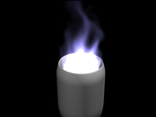
The plasma looks a bit too bright so it's hard to see the cone in the center. No problem though. The opacity and color of the fire can be tweaked interactively within the viewport.
Go back to the Rendering tab in the FumeFX UI.
Change the Opacity spinner value from 0.1 down to 0.07.
The image updates right inside the 3ds Max viewport. That's because the simulation data is on your hard disk and FumeFX can update the output data in the viewport without having to re-simulate the data. This is incredibly powerful when you want to tweak settings such as color and opacity.
Next, re-open the Opacity AFC window and change the curve to match this following image.
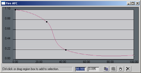
Again, the viewport will update to show you the changes to your flames as you add and move the knots in the Opacity gradient around.
If you render scene, you will notice banding artifacts on the plasma tendrils. To get rid of them, you will need to increase rendering quality.
Open Rendering tab and change Step Size % to 20 and Jittering to 20.
Now, let's say that the client decides that blue isn't the color they really want - they want it to be green. No problem.
Click on the Color gradient swatch again, and change it as follows:
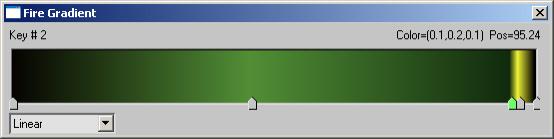
When you render again, the plasma fire will have changed color, and you didn't have to re-sim!
What makes this SO powerful is that it frees you to make changes to various aspects of your simulation after you've run it. This should unleash your creative side and let you tweak until you've got it just how you envisioned the effect looking.
Adding Post Effects
Next, we're going to add a Lens Effects glow to this plasma to give it some "bloom" in a final render. In order to do this, you'll need to do a few things:
Assign an Effects Channel to the simulation.
Tell FusionWorks to generate Effects Channels.
Build the Lens Effects Glow effect and make it key off of the Effect channel set in FumeFX.
Let's get started.
Within the FumeFX UI floating dialog, go to the Rendering tab.
Under the Rendering Parameters rollout, change the Material ID spinner value to 1.
Now, go to your 3ds Max environment tab (hit '8' as a quick shortcut to get to it).
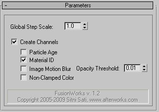
Within this dialog, you'll find the FusionWorks Renderer listed under the Atmospheric effects. It is placed there automatically when you start working with FumeFX. In order to get a glow effect to work, you FusionWorks needs to generate channels for use by other post process effects like glows.
Highlight the FusionWorks Renderer and from the Parameters rollout, click in the Create Channels checkbox to activate it.
Next, activate the Material ID checkbox as well.
Now that the effect channel can be created, it's time to add the Lens Effects Glow to your FumeFX output.
Click on the Effects tab in the Environment and Effects dialog, and hit Add. Choose Lens Effects from the pop-up dialog.
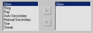
Now, within the Lens Effects Parameters rollout, highlight the Glow element and hit the arrow to add it to the active effects.
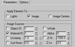
Next, scroll down to the Glow Element rollout, and click on the Options tab.
Within the Apply Element To: group of controls, choose Image. Turn the other checkboxes off if they are on.
Now under the Image Sources group of controls, activate the checkbox for Material ID, and change its spinner value to 1. This will match the Effects Channel you set earlier inside of the FumeFX UI floating dialog.
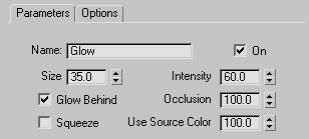
Go back to the Parameters tab within the Glow Element rollout.
Change the Size spinner to 35.0, the Intensity spinner to 60 and the Use Source Color to 100. We want the glow to match the color of the original FumeFX output.
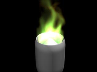
Render a frame.
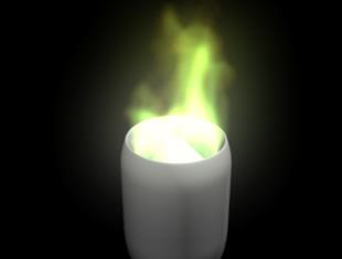
As you can see, the glow effect has been applied to your plasma fire.
In the next tutorial, you'll take the next step in learning FumeFX by adding maps to your simulations to help add even more realism. Also, you'll learn how to generate simulations that contain nothing but smoke.