Swirling Particles With Custom Voxel Field
OVERVIEW
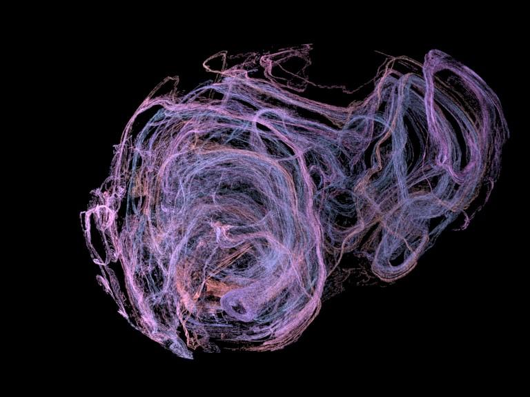
In this FumeFX 6 tutorial we are going to create a custom swirly velocity field that will be used to advect millions of particles and we will show how to render those particles as points by using the Arnold renderer point primitive. We are going to use displaced Geo Sphere and it’s vertices to generate swirling velocity voxel field. Displacement is animated so that we get a dynamics effect that changes over time..
SCENE SETUP
In 3ds Max, select File->Open, and from your /Scenes/FumeFX/ Tutorials folder, select the file Tut_17_start.max

Create a NodeWorks in the new scene and open editor.
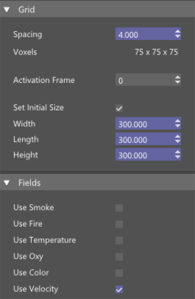
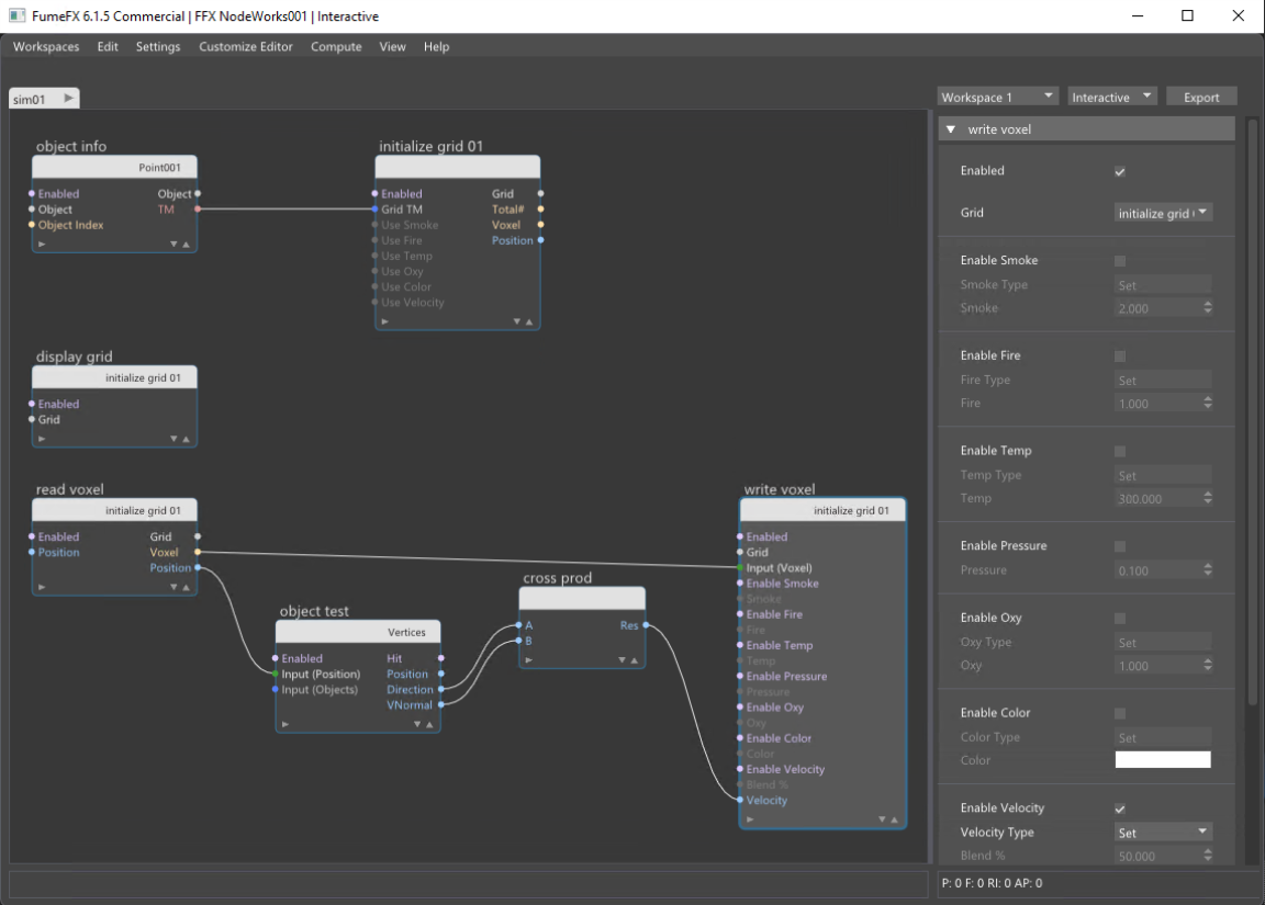
Now we need to create a voxel field by using the Initialize Grid node. This node will create an empty voxel grid with user defined channels. We will need only velocity field, so we can disable the smoke channel. We don’t need lots of detail so set all three sizes to 300 and grid spacing to 4. This will result in a voxel field that has 75 voxels along each axis.
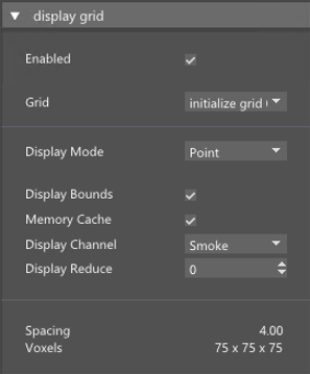
Voxel grids can be visualized by using the Display Grid node, so let’s create one and for now just display the voxel grid bounds.
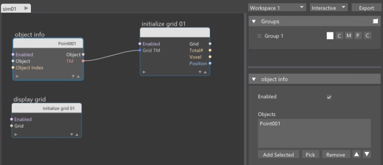
Since the initial grid position is at 0,0,0 we will need to move the grid so that the geo sphere with animated displacement modifier is placed inside the voxel grid as we’re going to use it to create velocities. Voxel grid can be positioned in the scene by supplying the transformation matrix and we are going to create position helper and use Object Info node to pass the helper transformation matrix into the Grid TM input of the Initialize Grid node. Since transformation matrix contains all the information about position, rotation and scale of the helper, our grid will inherit those properties directly so we can easily place it wherever we need it.
In our setup instead of one vertex we have geo sphere with many vertices. For each voxel in the grid, we will need to get voxel position, closest vertex on the geo sphere and vertex normal.
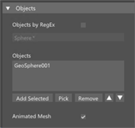
First we have to create a Read Voxel node to access each voxel and its position. For each voxel in the grid we are going to pass its position to the Object Test node that will find the closest vertex on the surface of the geo and to do that we will set it to the Vertices mode. For now we will use normal only from the closest vertex but we could also use the average from user defined number of vertices which I’m going to use later. Object test node will also output vertex normal so now we have all components that we need to solve our task - voxel position, closest vertex normal and direction from vertex to voxel.

To calculate vector product of two vectors we will use a Cross Product node. Connect Direction to the A input and Vertex Normal to the B input pin. Direction pin will output vector that goes from voxel center to vertex. We need to normalize output and set scale of 3. With this scale we will control the magnitude of the velocity that we’re going to write into the voxels. Connect output from Cross Product node to Velocity pin in Write voxel node. Also, connect Read Voxel and Write Voxels through voxels pin (see the image below). Enable Velocity in Write Voxel node.
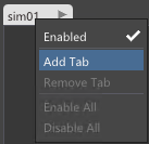
Now we’re going to create a new tab where we’ll work with splines and particles.
![]()
First we will need to create some particles that will be anchors for the Voxel Trail splines.
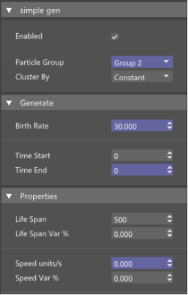
Use a Simple Gen node, set velocities to zero as we don’t want particles to have any initial velocity. Those particles will need to be created only once, at frame 0 so both Time Start and Time End must be zero. Set Birth rate to 30 which will generate 30 particles in total.
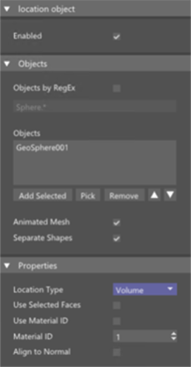
Drag output and create Location Object node. Add GeoSphere object and change location type to Volume. This option will position particles inside the volume of the geo sphere. To actually move particles to new positions we need Position node.

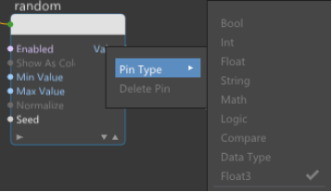
And now we can finally create voxel trail node. This node requires particles which will be used as origins of splines that will grow along velocities inside the grid. Thus we need to create Get Part group node to access particles and their positions at each frame. We want each spline to have different color so we will need the Random node. Connect particle group with a random node. Change pin type to Float3 and enable Show as Colors. Change colors as you like.
|
|
|
|

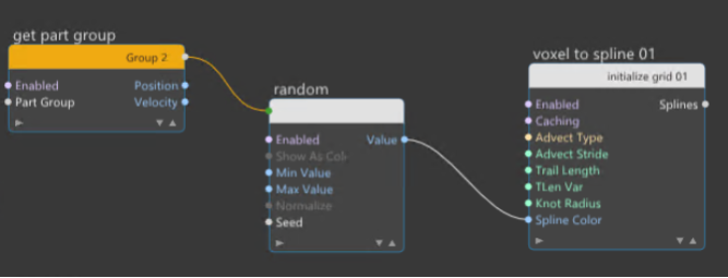
Connect result Value to the Voxel Trail Spline Color pin and connect particle pins.
As you can see, particle flow is now automatically connected with Voxel Trail node and you don’t need to make this connection manually which creates much cleaner layout.
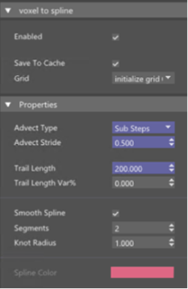
The trail shape will greatly depend on the Advection Type and stride but for this scene, Sub Steps and stride of 0.5 will work just fine. Currently, splines are very short and we can lengthen them by increasing the trail length value. We are using the 200 here but you can use whatever works for you.

Now when all is nice and colorful we can see that some swirls have small radius and we want them to be a little bit bigger with less abrupt changes. To change this we need to go back to first Tab and Object Test node and use Output Averages option. As we will increase the number of Max. Vertices the splines shapes are changing quite dramatically. The more vertices we average the smoother grid velocities will be. We can even use the max distance to reject all vertices from the search that are further away from the voxel which allows us complete control over evaluation. If we increase max distance then all vertices regardless of their distance from the voxel will be taken into consideration.

Now that we have splines what’s left to do is to generate particles on those splines. Create Spline Gen node that will generate particles into the first particle group. Second particle group is reserved for spline sources and if we would be generating into the same group there will be a loop that will end up in millions of splines and particles in just a few frames.
Particle will be generated each frame throughout 400 frames. We have different generation modes and we’ll use random that will place particles randomly over the spline length. Count of 1000 will generate a nice dense particle cloud and we are going to set velocities to zero as we’ll move particles along the grid by advection.
Life Span is set to 200 so that particles slowly disappear throughout the animation. As we can see, those particle are static – they don’t move yet .
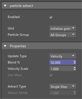
The Particle Advect node will be in charge of advecting particles along the voxel grid velocities. Advection is a process of moving quantities through the voxel grid by using stored velocities. FumeFX simulation uses advection as a crucial part of the simulation.
Update type will be velocity and we are going to set Blend to 50% which allows for an even smoother particle motion throughout the grid.
We are going to memory cache those particles so we can see the result. There are millions of particles so make sure that you don’t have too low Max Particles limit inside the NodeWorks simulation parameters, and plenty of memory to cache all those particles.
To see this a bit better we are going to setup rendering with Arnold.
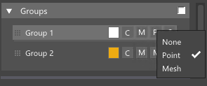
First of all set the particle group to render as point and from the Settings menu, Arnold points option we will set point scale to 0.05 and render mode as Sphere. Changing the point scale here has advantage over changing the particle size as this change will not trigger re-simulation of NodeWorks.
![]()
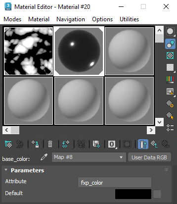
We’ll want to use particle colors for rendering so for the Arnold User Data export enable color option. From Material editor create a Standard Surface material, and for the Base color add User Data RGB and type fpx_color for the Attribute. Now we can directly control particle color from the NodeWorks. This is really amazing Arnold feature and NodeWorks fully utilize Arnold renderer capabilities.
Open up the Arnold render view so that we can see how our setup looks rendered.
Now when we look at this simulation, there might be too many particles so we will go back and decrease particle lifespan from 200 to 50 and increase number of particle to 3000 for example. You could also reduce number of particles for splines, so we’ll have less splines.
If you want very smooth trails, increase the number of Max. Vertices and Max. Distance.