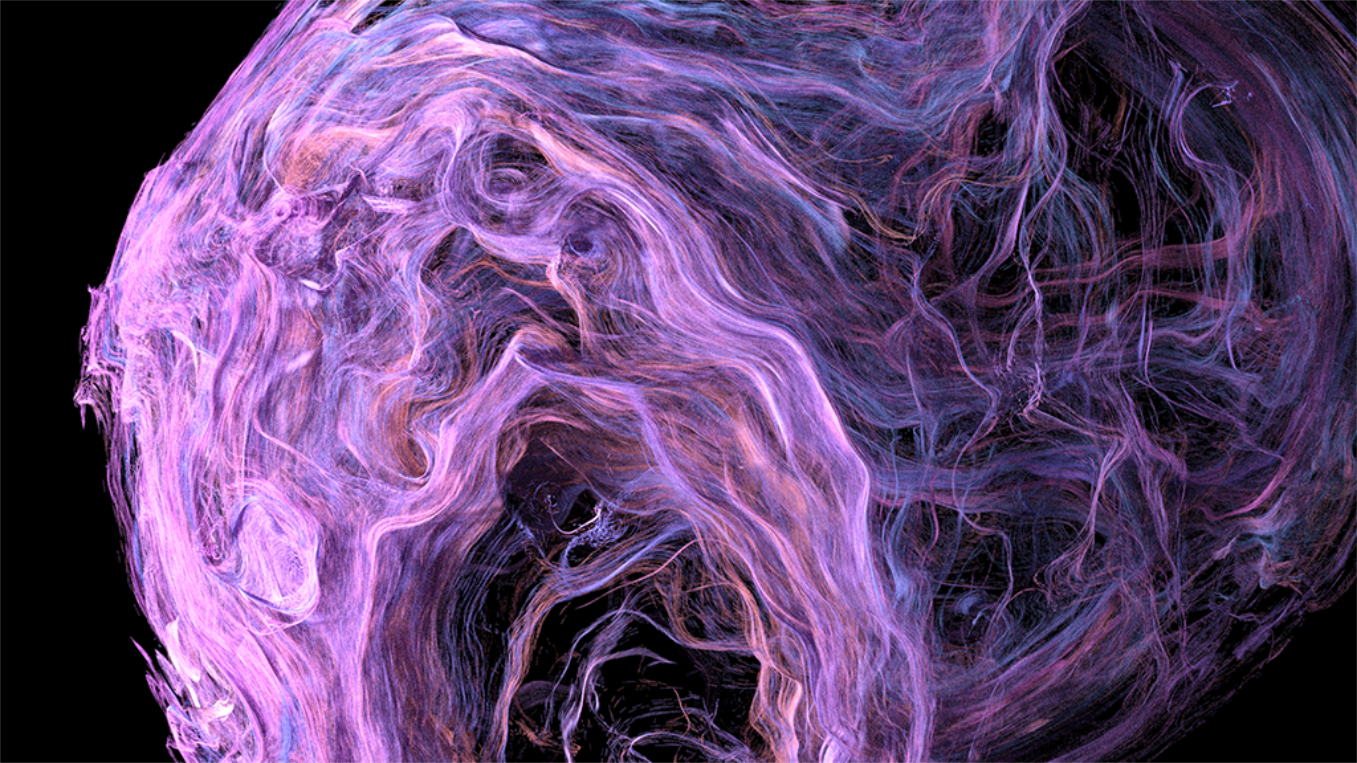
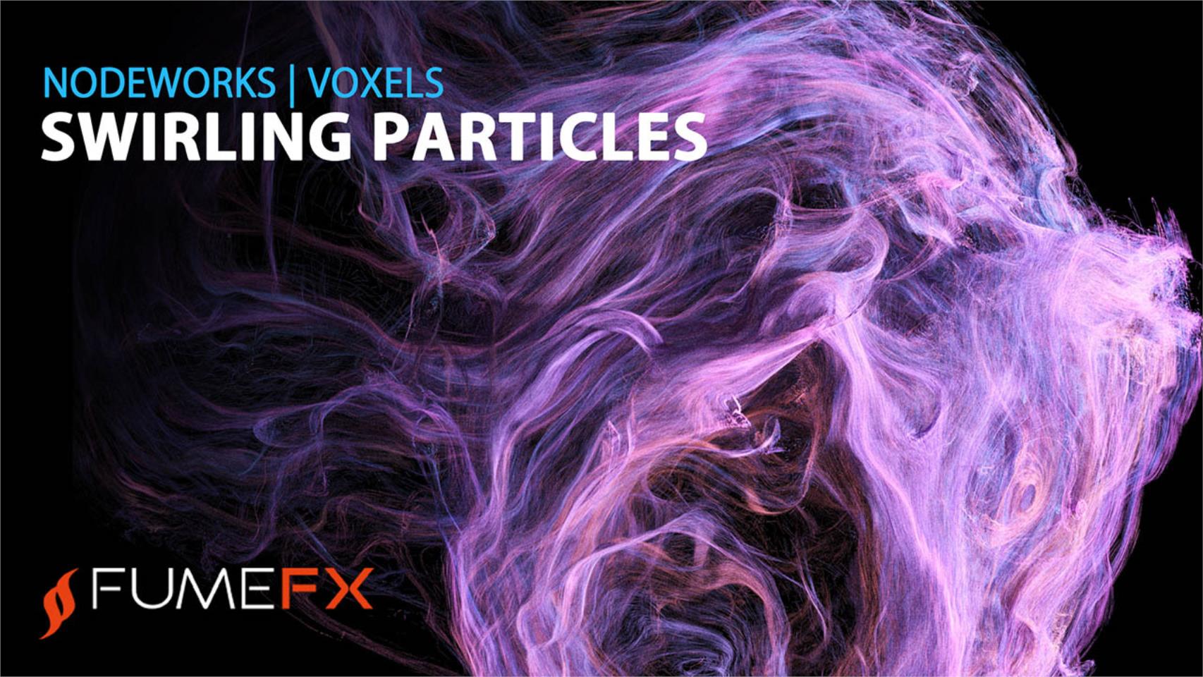
Swirling Particles & Custom Voxel Field
In this FumeFX 6 tutorial for 3ds max we are going to create a custom swirly velocity field that will be used to advect millions of particles and we will teach you how to render those particles as points by using the Arnold renderer point primitive. We are going to use displaced Geo Sphere and its vertices to generate swirling velocity voxel field. Displacement is animated so that we get a dynamic effect that changes over time.
Create empty voxel grid
For a start you will need a startup file that can be downloaded from: https://bit.ly/3uXChc8
In 3ds max, select File->Open, and the file Swirl_tut_start.max
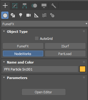
Go to the Create Command Panel, select FumeFX from the dropdown list, then click on the NodeWorks button.
Create NodeWorks in the scene and click on the Open Editor button to open the node editor.
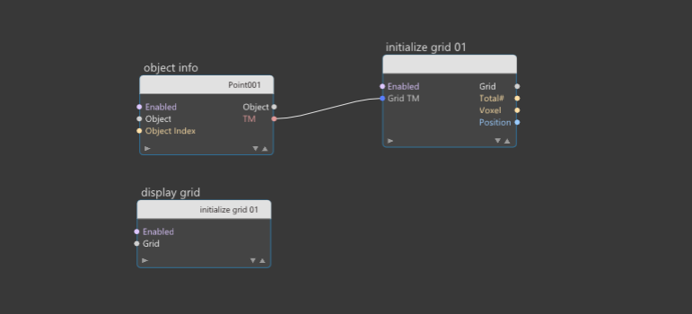
Our first task in this tutorial will be to create a setup that will create an empty voxel grid as well as a node that will help us to visualize its content within the 3ds max viewport.
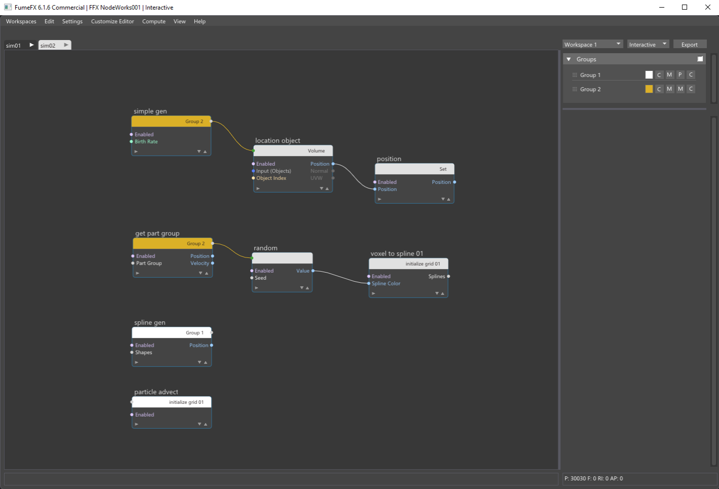
The final setup is show on the image on the right and we`ll guide you step-by-step how to create those nodes, connect them and how to setup attributes.
To create the voxel field we are going to use the Initialize Grid node. This node will create an empty voxel grid with user defined channels.
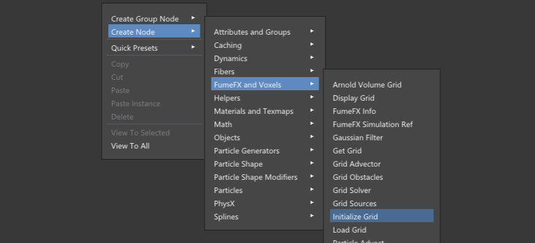
To Create this node, right click on an empty node editor area, go to the Create Node -> FumeFX and Voxels - > Initialize Grid menu option. Once you click on the node name a new node will be created at your mouse position.
Within the NodeWorks editor all nodes can be also created if you press a TAB key and start typing the node name ??? in this case Initialize Grid. As you type the node name, the list of listed nodes will shorten leaving only nodes with matching names.
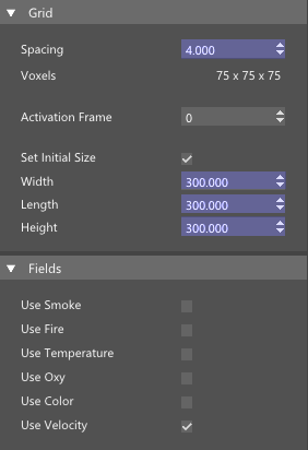
For this tutorial we will need only a velocity field, so we can disable smoke, fire and other channels and leave Use Velocity enabled. We don`t need lots of detail so set Width, Length and Height to 300 and Grid Spacing to 4.0. This will result in a voxel field that has 75 voxels along each axis which you can read below Spacing control. Activation Frame will be left to 0 which means that all the voxel grid fields will be created at frame 0.
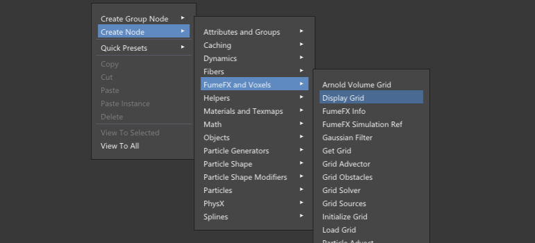
Voxel grids can be visualized by using the Display Grid node, so let`s create one. Right click on an empty node editor area, go to the Create Node menu -> FumeFX and Voxels - > Display Grid.
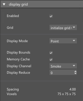
Once you create the Display Grid node you can see that under the Grid combo box initialize grid 01 has been automatically added and selected. If there is more than one voxel grid in the scene you will need to manually choose which grid is going to be displayed within the 3ds max viewport.
Currently, the voxel grid is empty and does not contain any data, but with Display Bounds option enabled we can see where the grid is located and where its bounds are.
By default, voxel grid is created at 0,0,0 coordinates and what we`re going to do next is to place voxel grid to a different location.
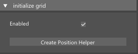
We will need to move the grid so that the geo sphere with animated displacement modifier is placed inside the voxel grid as we`re going to use it to create velocities. Voxel grid can be positioned in the scene by supplying the transformation matrix and we are going to create position helper and use Object Info node to pass the helper transformation matrix into the Grid TM input of the Initialize Grid node. Since transformation matrix contains all the information about position, rotation and scale of the helper, our grid will inherit those properties directly so we can easily place it wherever we need it.
The easiest way to create Object Info node with position helper is to press the Create Position Helper button located inside the Initialize Grid node.
By pressing this button a Position helper will be create in the scene and it will be automatically added to the newly created Object Info node. Transformation matrix pins named TM will be connected between Object Info and Initialize Grid node.
What is left to do is to select the position helper and place it at the location such that GeoSphere is placed entirely inside the voxel grid boundaries.

Math Behind the Swirling Effect
Before proceeding let`s take a quick look at the math used for this tutorial.
The operation we are going to use to create a swirly vector field is a vector product or cross product - both words mean the same operation. The cross product of two vectors is also a vector but such a vector that is perpendicular to the plane those two vectors form. One simple example is the coordinate axis where X and Y vectors are on the XY plane and Z vector is perpendicular to the XY plane. Finding the direction of the cross product can be determined by the so-called right hand rule. Vector A cross vector B results in vector C, but B cross A results in C that points in opposite direction. Keep that in mind.
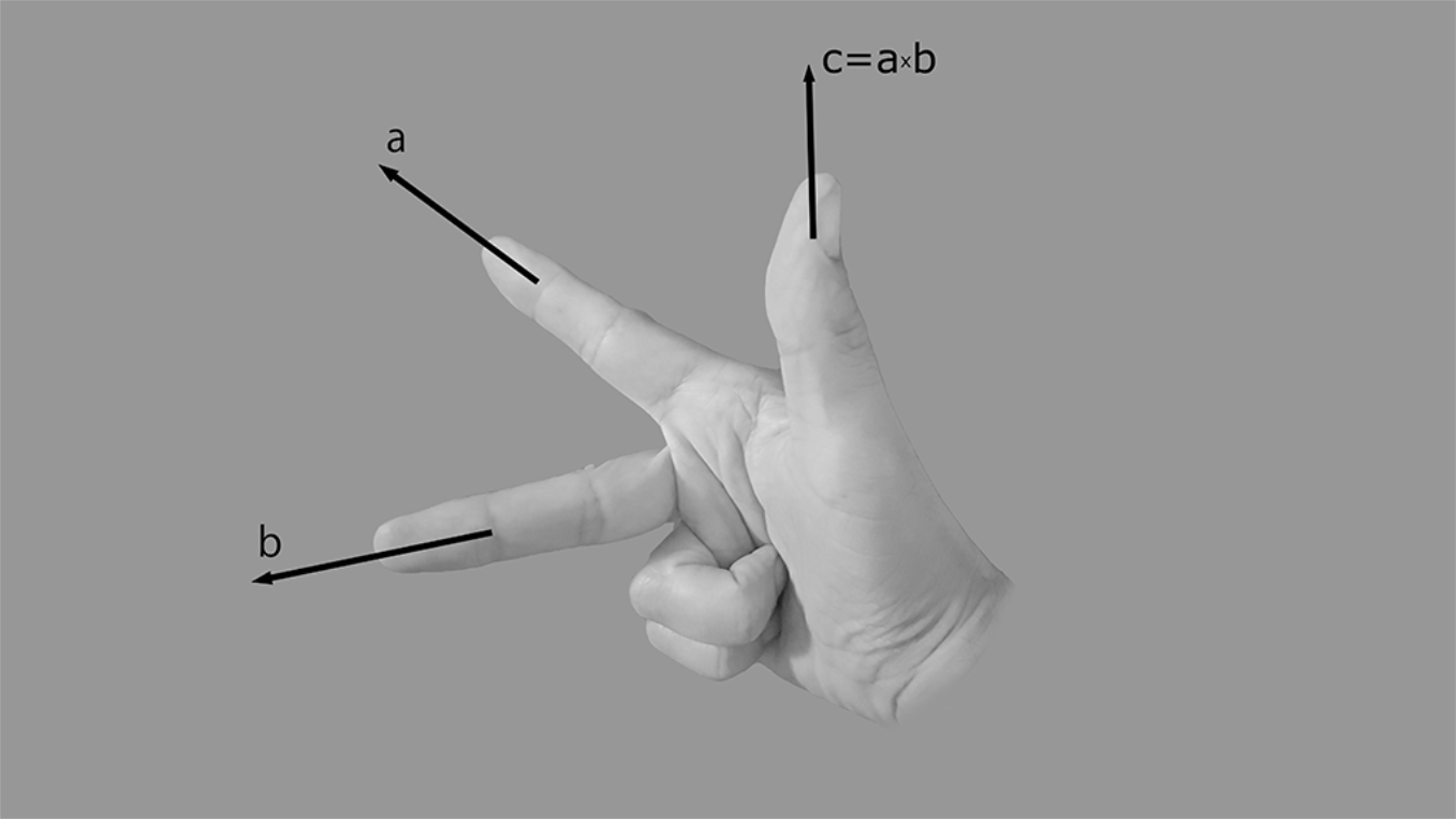
The two vectors we are going to use are the vertex normal (blue) and vector that connects vertex and voxel center (green). On the image below you can see the cross product as orange line. This operation gives us a circular field around vertex. In this case input vectors do not need to be normalized, but output does as its magnitude will change with the distance of the voxel center from vertex. If we normalize result of the cross product you the vector length remains the same regardless of the distance of voxel from the vertex.

Creating New Voxel Field

In our scene we have a geo sphere with many vertices. For each voxel in the grid, we will need to get voxel position, closest vertex on the geo sphere and vertex normal.
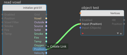
First we have to create a Read Voxel node to access each voxel and its position. To create that node, press TAB and start typing Read Voxel. When the node shows up in the list, click on its name to create it.
Again, press that TAB key and start typing Test and it will narrow down the search to a few nodes. Select Object Test from the list and create Object Test node. Place it in a position as shown in the image on the right.
Now we need to connect position pins for both nodes to pass voxel position to Object Test node. Click on the Input (Position) pin of the Object Test node and drag connection over the Read Voxel node. This drag will initiate that Read Voxel node displays all of its pins so that you can create a connection with its Position output pin. Once the connection is created, unconnected pins will be hidden. At any time you can click on the node display style arrows  to expand or contract pins list.
From Object Test node, Pick GeoSphere001 object, set Test Type to Vertices and set Max. Distance to 100.0.
Using this setup, for each voxel in the grid we are going to pass voxel position to the Object Test node that will find the closest vertex on the surface of the GeoSphere.
For now we will leave Output Averages unchecked so we will use normal from the closest vertex only. Object test node outputs vertex normal so now we have all components that we need to solve our task - voxel position, closest vertex normal and direction from vertex to voxel.
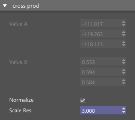
To calculate vector product of two vectors we will use a Cross Product node.
Create Cross Prod node next to the Object Test node.
Connect Object Test Direction pin to the A input and VNormal to the B input pin. Direction pin will output vector that goes from voxel center to vertex.
We need to enable Normalize output and set Scale Res to 3. With this scale we will control the magnitude of the velocity that we`re going to write into the voxels.
To complete this setup we need to write resulting vector to voxel velocity so create the Write Voxel node next to the Cross Prod node.
Connect Res from Cross Product node to Velocity pin in Write voxel node. Also, connect Read Voxel and Write Voxels through voxels pin (see the image below). Enable Velocity in Write Voxel node.
From Object Test node drag connection from the Hit pin to the Write Voxel Enabled pin. This will disable Write Voxel node in the case were particle is further away than Max. Distance (100.0) from the GeoSphere vertices.
Finally, connect Voxel pins between Read Voxel and Write Voxel nodes.
On the image below you can see the final configuration that will generate custom velocity field inside our voxel grid.

Creating Splines Along Velocity Field
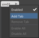
Now we`re going to create a new tab where we`ll work with splines and particles. To create a new tab, right click next to the existing sim01 tab and select the Add Tab menu option.
This will create new tab which helps us to visually separate different setups. Although you can create all nodes within one tab, it`s recommended that you use tabs as they allow faster navigation through various node networks which can quickly become very complex.
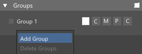
First we will need to create particles that will be anchors for the Voxel Trail splines. To create a new particle group, right click below Group 1 and choose Add Group menu option.
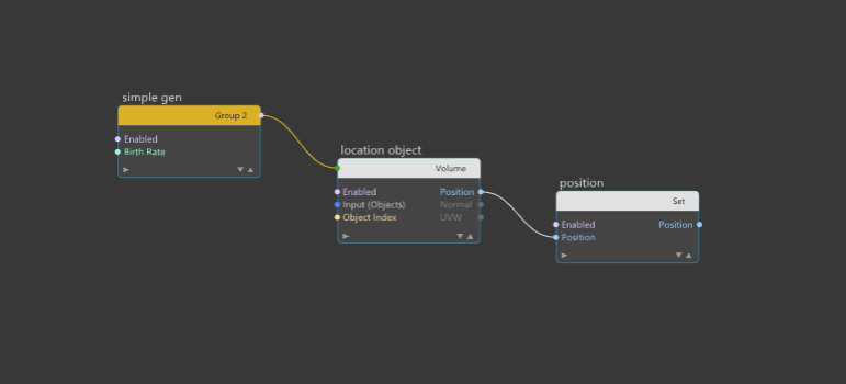
Our next task will be a simple setup that will generate particles inside the GeoSphere object.
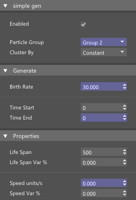
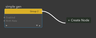
As a particle generator we will use a Simple Gen node which you can create by using the TAB key and start typing the Simple Gen.
This generator node will output particles into the Group 2, so from the Particle Group combo box select Group 2.
Those particles will need to be created only once, at frame 0 so both Time Start and Time End must be zero.
Set Birth Rate to 30 which will generate 30 particles in total at frame zero. .
Set Speed to 0.0 as we don`t want particles to have any initial velocity.

Now we are going to create the Location Object node and we can do that if you click on the particle stream output pin located at the right side of the Simple Gen node header.
Once you have dragged connection to a place where you want to create a new node, release the mouse button and select Objects -> Location Object node. You can also create a node if you press the TAB key after you have released the mouse button.
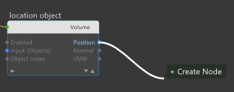
From the Location Object node press the Pick button and add the GeoSphere001 object. Change Location Type to Volume. This option will position particles inside the volume of the geo sphere. To actually move particles to new positions we need to create Position node.
From the Position output pin of the Location Object node drag connection to a location where you want new node to be created. Release the mouse button, press TAB key and start typing Position. Select Position node from the list to create it. In this case Position node must be in Set Mode as we will write to particle position attribute.
 .
.
The next setup we`re going to create will use Group 2 particles as birth location for splines that will follow voxel field velocities by using the Voxel to Spline node.
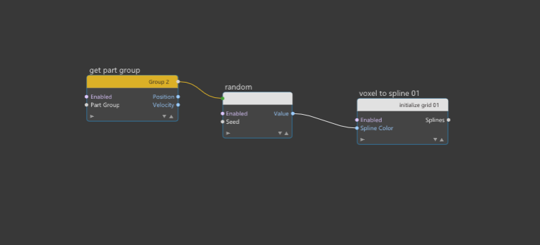
Create Get Part Group node and set Particle Group to Group 2.
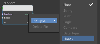
We want each spline to have different color so we will need the Random node. From the Get Part Group node particle stream output pin, drag a connection and create a Random node.
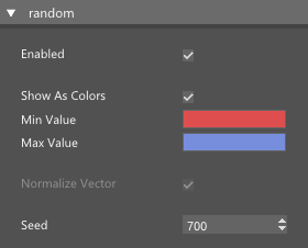
Right click on the Value output pin and change pin type to Float3 and enable Show as Colors. Change Min. Value and Max. Value colors as you like.
Drag the Random node Value output pin and create the Voxel to Spline node.
As you can see, particle flow is now automatically connected with Voxel to Spline node and you don`t need to make this connection manually which creates much cleaner layout.
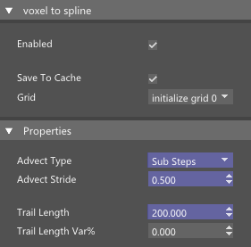
The trail shape will greatly depend on the Advection Type and stride but for this scene, set Advect Type to Sub Steps and Advect Stride to 0.5.
Currently, splines are very short and we can lengthen them by increasing the trail length value.
Increase Trail Length value to 200 but you can experiment with different values and choose the one that works the best for you.
Now when all is nice and colorful we can see that some swirls have small radius and we want them to be a little bit bigger with less abrupt changes.
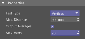
To change this we need to go back to first Tab and Object Test node and enable the Output Averages option. As we will increase the number of Max. Verts the splines shapes are changing quite dramatically. The more vertices we average the smoother grid velocities will be.
For this tutorial set the Max. Verts to 20. We can even use the max distance to reject all vertices from the search that are further away from the voxel which allows us complete control over evaluation.
If we increase Max. Distance to 999 then all vertices regardless of their distance from the voxel will be taken into consideration.

Generate Particles on Splines
Now that we have splines what`s left to do is to generate particles on those splines.
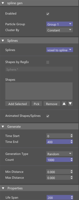
Create Spline Gen node and set Particle Group to Group 1.
This will generate particles into the first particle group. Second particle group is reserved for spline sources and if we would be generating into the same group there will be a loop that will end up in millions of splines and particles in just a few frames.
Under the Splines rollout set Splines to voxel to spline 001. This will tell this node to use our NodeWorks splines as particle spawn locations
This node can also spawn particles from 3ds max shapes but this won`t be used in this tutorial.
Particle will be generated each frame throughout 400 frames so set Time End to 400. We have different Generation Types and we`ll use random that will place particles randomly over the spline length.
Set Count to 1000 which will generate a nice dense particle cloud and we are going to set velocities to zero as we`ll move particles along the grid by advection.
Life Span is set to 200 so that particles slowly disappear throughout the animation.
By default Color From Spline option is enabled which will cause particle to inherit color from the spline where it was created.
At this point we can see that all those particles are static - they don`t move and we want them to move along the voxel field velocities.
Advecting Particles by Voxel Field
Move your mouse pointer below the Spline Gen node, press TAB key and type Particle Advect.
From the list, select the Particle Advect node to create it.
This node will be in charge of transporting particles along the voxel grid velocities. Advection is a process of moving particles through the voxel grid by using stored velocities. FumeFX simulation uses advection as a crucial part of the fluid simulation.
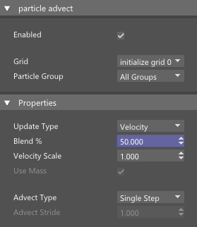
Set Particle Group to Group 1 as we only want to advect particles that are created on the spline with the Spline Gen node.
Set Update Type to velocity and set Blend to 50% which allows for an even smoother particle motion throughout the grid.
We are going to memory cache those particles so we can see the result. There are millions of particles so make sure that you don`t have too low Max Particles limit inside the NodeWorks simulation parameters (Settings - > Simulation), and plenty of memory to cache all those particles.
Rendering Particles as Arnold Points With User Defined Colors
To see this a bit better we are going to setup rendering with Arnold renderer.
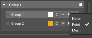
First of all set the particle group to render as point by clicking on the second button with M letter on the right side of the particle group name.

From the Settings -> Arnold Points menu option set Point Scale to 0.05 and Render Mode as Sphere. Changing the point scale here has advantage over changing the particle size as this change will not trigger re-simulation of NodeWorks.
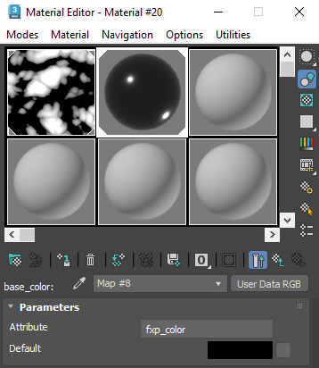
We`ll want to use particle colors for rendering so from the Settings - > Arnold User Data Export menu option enable Color option. From Material editor create
Arnold`s Standard Surface material, and for the Base color add User Data RGB and type fpx_color for the Attribute. Now we can directly control particle color from the NodeWorks. This is really amazing Arnold feature and NodeWorks fully utilize Arnold renderer capabilities.
Open up the Arnold render view so that we can see how our setup looks rendered.
Now when we look at this simulation, there might be too many particles so we will go back and decrease particle lifespan from 200 to 50 and increase number of particle to 3000 for example. You could also reduce number of particles for splines, so we`ll have less splines.
If you want very smooth trails, increase the number of Max. Vertices and Max. Distance.