Simulation
Simulation
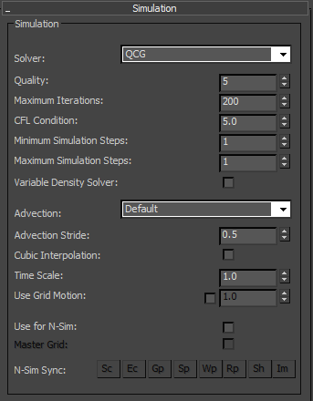
Solver – FumeFX offers two solvers: CG and QCG.
Both solvers are based on the conjugate gradient method and the main difference between those two solvers is the solving speed. QCG is much faster than the original CG which was left inside the FumeFX for backward compatibility. We strongly recommend usage of the QCG solver.
Quality - This parameter defines the simulation realism. Higher quality increases realism at the cost of increased computation and slower simulation performance. It is advisable to increase quality for fast moving objects.
Higher Quality values will enable the Solver to perform more simulation iterations to achieve a more accurate solution of the fluid dynamics equations. Using a low value for Maximum Iterations may limit the number of iterations when using high Quality values.
To allow the solver to always reach the quality set by the user, you might want to keep Maximum Iterations at maximum value.
Simulation Status Window message “CG done with nnn iterations” will tell you if solver iterations are limited by Maximum Iterations parameter.
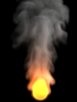
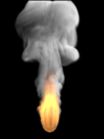
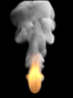
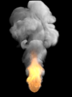
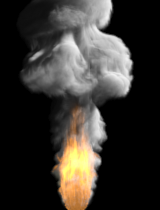
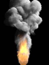
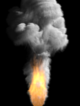
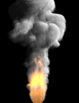
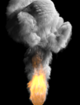
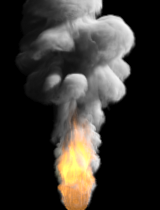
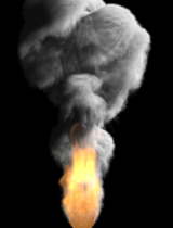
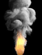
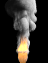
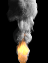
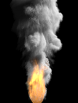
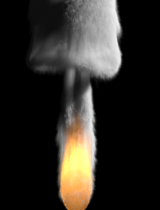
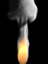
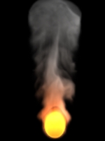
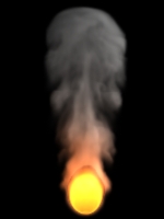
Maximum Iterations - This parameter sets the maximum number of iterations the solver can complete. If not bounded by this parameter, the solver will automatically stop when it reaches an acceptable level of accuracy defined with Quality parameter. The solver does not need many iterations to achieve good results (20-30 for small grids, 100 for bigger grids, or fast sources/objects). To create sample images, we used Quality=5 and solver required more than 100 iterations to reach it.
|
|
|
|
|
Max. Iterations: 10 |
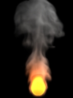
Max. Iterations: 30 |
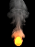
Max. Iterations: 100 |
CFL Condition - This value defines the maximum distance allowed for any cell data (velocity, smoke, fire, etc..) to travel in one simulation step. This number has a direct influence on the number of Simulation Steps. For example, if you use the CFL number 5, it would mean that if the system detects any velocity inside the voxel grid that will result in a field to travel more than 5 voxels in one simulation step, the simulation step will be divided so that the the distance does not exceed this number. Generally, simulation is stable when CFL number is kept between 4 and 5, but unless you notice artifacts, much bigger values can be used as well. If you choose too small values you can expect the effect of blurring.
You have to keep in mind that by decreasing the Spacing value you actually decrease voxel dimensions. This will result in increase of simulation steps required to satisfy the CFL Condition, because velocities will be able to carry cell data to through more voxels.
It is not always an imperative to have many simulation steps as fluid motion can look convincing even with one. You always need to find the balance between simulation time and "mathematical correctness" of the simulation.
Minimum Simulation Steps – This parameter will set the minimum number of simulation steps, regardless of the CFL Condition value.
Maximum Simulation Steps – The number of steps is directly controlled through CFL Condition parameter value, but with this parameter, you can limit maximum number of steps.
Variable Density Solver - We all know that high density fluid will be able to penetrate into the low density fluid much more that the way around. In FumeFX you can account for temperature and smoke density to simulate such behavior. For easier effect control, we recommend that you either use vd Smoke Multiplier or vd Temp Multiplier. To disable Variable Density solver for either smoke of temperature, simply set vd Multiplier to zero. Keep in mind that enabling this option could increase time for solver to get to the solution as it has to account for additional divergence that is created.
Advection
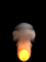
Default advection is a good all-purpose advection, but it generates visible dissipation.
Advanced (fields) advection that will result in lower dissipation. This advection operates on fire, smoke and temperature fields, while velocities are still advected using Default advection.
Advanced (fields and vels) advection operates on all fields and velocities as well. This type of advection is excellent for slow moving fluids while highly divergent and fast moving fields might result in artifacts in the form of lines or crosses (see image below). Keep in mind that this advection is very good in preserving small scale detail, so the vorticity value can be kept really low (around 0.1).
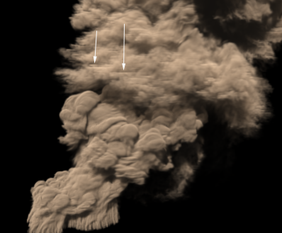
On the image above you can notice horizontal lines caused by the fast smoke motion using Advanced (fields and vels) advection.
TIP: Here are few approaches that might help to get rid of artifacts if they show up. First of all, you can try lowering the adaptive grid sensitivity to 0.01 or even to 0.0. This should help because velocity fields close to the grid boundaries tend to be much smoother. If that does not help, you can try to switch to the Advanced (fields) advection, increase solver Quality or even switch back to the Default advection.
Advection Stride - The lower this stride is, the less dissipation of velocity and smoke will happen, but it will take more time to compute advection. This value is relative to Grid Spacing.
TIP: For smoke with many small curls you may want to decrease this number to 0.1 or less.
Cubic Interpolation - If you need better quality, you will want to check this option. Simulation times will rise considerably, but less dissipation will occur and more swirls will be created. Whenever you use any type of Advanced advection, cubic interpolation will be used for the velocity field, while linear interpolation will be used for smoke, fire and temperature.
Time Scale - Use this to speed up or slow down the passage of time during simulation. If you set it to 0, the simulation comes to a halt; set a higher value to increase speed. If you accelerate time by some significant amount (>1.5x), you will have to increase the simulation steps as well to preserve stability and continuity. Also, note that you can animate this parameter.
Use Grid Motion – Enable this option if you want FumeFX fields to be affected by the grid motion. It allows user to create effects like falling comet, rocket launch etc. by using container that is linked to the source.
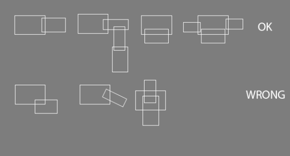
Use for N-Sim – FumeFX supports simulation of nested grids. To be able to use N-Sim, this option has to be enabled. Also, grids have to overlap and they must be axis aligned (no rotation) as shown on the image below.
You should arrange grids to overlap by at least 10% as too little overlap may cause more abrupt transitions from one grid to another.
If using “Boundless” grid option, the expansion along overlapping axis will be disabled.
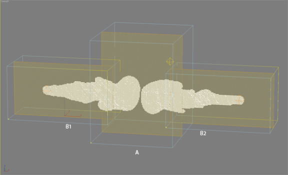
In the case that “Use for N-Sim” option is disabled, the FumeFX grid will not participate in N-Sim even if it overlaps with the master grid. On the image below we have selected A grid as a “master” grid which automatically drives simulation of “child” grids B1 and B2.
Master Grid – Select the grid that will always be the main grid in the simulation. Other grids with only Use for N-Sim option selected will not be able to run simulations.
N-Sim Syncing – This option allows a user to sync all child parameters with the master grid. This comes in handy if you keep changing parameters in your master grid and want to propagate those to all children automatically. If this operation has overwritten a child’s parameters by mistake, there is an undo option in the 3ds max’s Undo menu named “Undo N-Sim Params Syncing” that will restore parameters to previous values.
If selected, Rendering, Shader and Illumination parameters will be synced during Preview Window update as well as during rendering. There is no undo for this type of sync operation.
N-Sim Sync
Sc (Simulated Channels) – sync which channels are going to be simulated.
Ec (Exported Channels) – sync list of channels that will be exported.
Gp - sync General Parameters tab parameters, except Width, Length, Height and 3ds max Script.
Sp – sync parameters from the Simulation Parameters tab. It will preserve the on/off states of the child’s simulated channels like Fire, Smoke and Color which can be controlled by enabling “Sc” option. Blocking Sides won’t be synced as well.
Wp – sync WTP Parameters tab parameters.
Rp – sync Rendering Parameters tab parameters.
Sh – sync Shader parameters.
Im – sync Illumination Parameters tab, including lights.
You can enable all of the buttons if you hold the left Shift key and left mouse click on any of the sync options. They can all be disabled if you hold the left Ctrl key down and left mouse click on any of the sync options.
System
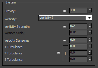
Gravity - This value defines gravity strength. The resulting force of gravity on a fluid causes buoyancy. That means that the fluid that has a different density that the surrounding will rise or fall. Hot air from fire has lower density than the surrounding air which causes it to rise. The influence of gravity is that it multiplies Smoke, Fuel and Temperature buoyancy values. Note that in zero gravity, there is no buoyancy!
Vorticity - This parameter is very useful for coarse grids when simulation lacks detail.
With increased grid detail the need for vorticity is lower as the simulation itself produces more detail. Higher vorticity will increase the number and strength of small vortices in the fluid.
FumeFX offers two different Vorticity types.
Vorticity I
Strength – This parameter is used to control the amount of small scale vortices that are added to the simulation. High values might cause smoke to dissipate and decelerate.
|
|
|
|
|
Strength: 0.0 |
Strength: 0.2 |
Strength: 1.0 |
Vorticity II
Vortices Scale - This parameter controls the scale of generated vortices. Higher values will tend to create a stream like motion while small values will tend to spread the motion outwards.
Note: It is recommended that the Vortices Scale parameter stays below value of 0.5 and that the ratio of Strength and Vortices Scale does not exceed 50. If this parameter’s value is above 0.5 or ratio becomes higher than 50, a warning asterisk symbol will appear in front of the Vortices Scale spinner.
|
Stren: 0.2 Scale: 0.001 |
Stren: 0.5 Scale: 0.001 |
Stren: 1.0 Scale: 0.001 |
|
Stren: 0.2 Scale: 0.01 |
Stren:0.5 Scale: 0.01 |
Stren: 1.0 Scale: 0.01 |
|
Stren: 0.2 Scale: 0.1 |
Stren: 0.5 Scale: 0.1 |
Stren: 1.0 Scale: 0.1 |
|
Stren: 0.2 Scale: 0.5 |
Stren: 0.5 Scale: 0.5 |
Stren: 1.0 Scale: 0.5 |
|
Stren: 0.2 Scale: 1.0 |
Stren: 0.5 Scale: 1.0 |
Stren: 1.0 Scale: 1.0 |
Velocity Damping - This gradually slows down the speed of flow, simulating internal friction.
|
|
|
|
|
Damping: 0.0 |
Damping: 0.01 |
Damping: 0.1 |
X/Y/Z Turbulence - Add artificial disturbance to smoke and fire on each axis separately or on all together. The Turbulence Noise Group offers further modification.
Turbulence Noise
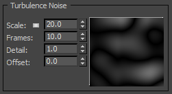
Scale - Set the scale for Noise, in world units. For a starting value, you can set Scale value to be 5 times bigger than the Grid Spacing value.
Frames - This value functions as a measure of speed for each phase change. Less frames means faster turbulence. For example, value of 25 would mean that turbulence will finish one 'cycle' in 25 frames.
Detail - Detail is equivalent to fractal noise levels. Set to a value greater than one if you do not see enough detail. This will, of course, slow down the simulation.
Offset - Use it to offset noise motion by specified value (in frames).
Noise Preview - It would closely match viewing FumeFX grid in the 3ds max viewport by using following options: XZ slice with Position=0, Thickness=1
Blocking Sides
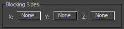
On each grid axis, you can choose to have zero, one, or two blocking sides. For example, if you set the Z-axis to "+Z" then top of the grid will act as a ceiling. If you set it back to none, the top of the grid will act as open space, letting smoke exit freely.